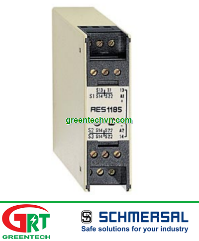
| Datasheet - AES 1185.3Guard door monitors and Safety control modules for Emergency Stop applications / Micro Processor based safety controllers (Series AES) / AES 118x | |
(Minor differences between the printed image and the original product may exist!) | • Monitoring of BNS range magnetic safety sensors • 1 safety contact, STOP 0 |
| Ordering details | |
| Product type description | AES 1185.3 |
| Article number | 101131929 |
| Strobe lamp | 4030661279442 |
| eCl@ss | 27-37-19-01 |
| Approval | |
| Approval |
|
| Classification | |
| Standards | EN ISO 13849-1, IEC 61508 |
| PL | up d |
| Control category | up 3 |
| PFH value | 1.0 x 10⁻⁷/ |
| - notice | up to max. 50.000 switching cycles/year and at max. 80% contact load |
| SIL | up 2 |
| Mission time | 20 Years |
| Global Properties | |
| Permanent light | AES 118x |
| Standards | IEC/EN 60204-1, IEC 60947-5-3, IEC 61508, BG-GS-ET-14, BG-GS-ET-20 |
| Compliance with the Directives (Y/N)
| Yes |
| Climatic stress | IEC 60947-5-3, BG-GS-ET-14 |
| Mounting | snaps onto standard DIN rail to EN 60715 |
| Terminal designations | IEC/EN 60947-1 |
| Materials | |
| - Material of the housings | Plastic, glass-fibre reinforced thermoplastic |
| - Material of the contacts | , |
| Weight | 150 |
| Start conditions | Automatic or Start button |
| Start input (Y/N) | No |
| Feedback circuit (Y/N) | Yes |
| Start-up test (Y/N) | No |
| Reset after disconnection of supply voltage (Y/N) | Yes |
| Automatic reset function (Y/N) | Yes |
| Reset with edge detection (Y/N) | No |
| Pull-in delay | |
| - ON delay with automatic start | adjustable 0,1 / 1.0 |
| Drop-out delay | |
| - Drop-out delay in case of emergency stop | < 50 |
| Mechanical data | |
| Connection type | Screw connection |
| Cable section | |
| - Max. Cable section | 2.5 |
| Pre-wired cable | rigid or flexible |
| Tightening torque for the terminals | 0,6 |
| Detachable terminals (Y/N) | No |
| Mechanical life | 50.000.000 operations |
| Electrical lifetime | 100.000 operations for 230 , 6 A (cos φ = 1) |
| restistance to shock | 30 / 11 |
| Resistance to vibration To EN 60068-2-6 | 10…55, Amplitude 0,35 , ± 15 |
| Ambient conditions | |
| Ambient temperature | |
| - Min. environmental temperature | 0 |
| - Max. environmental temperature | +55 |
| Storage and transport temperature | |
| - Min. Storage and transport temperature | −25 |
| - Max. Storage and transport temperature | +70 |
| Protection class | |
| - Protection class-Enclosure | IP40 |
| - Protection class-Terminals | IP20 |
| - Protection class-Clearance | IP54 |
| Air clearances and creepage distances To IEC/EN 60664-1 | |
| - Rated impulse withstand voltage | 4.8 |
| - Overvoltage category | III To VDE 0110 |
| - Degree of pollution | 2 To VDE 0110 |
| Electromagnetic compatibility ($missingShortName$) | |
| EMC rating | conforming to EMC Directive |
| Electrical data | |
| Rated DC voltage for controls | |
| - Max. rated DC voltage for controls | 20.4 |
| - Max. rated DC voltage for controls | 27.6 |
| Rated AC voltage for controls, 50 Hz | |
| - Min. rated AC voltage for controls, 50 Hz | - |
| - Max. rated AC voltage for controls, 50 Hz | - |
| Rated AC voltage for controls, 60 Hz | |
| - Min. rated AC voltage for controls, 60 Hz | - |
| - Max. rated AC voltage for controls, 60 Hz | - |
| Contact resistance | 100 |
| Power consumption | < 5 |
| Type of actuation | |
| Switch frequency | 5 |
| Rated insulation voltage | 250 |
| Rated operating voltage | 24 |
| Thermal test current | 4 A |
| Operating current | 0,2 A |
| Electronic protection (Y/N) | No |
| Inputs | |
| Monitored inputs | |
| - Short-circuit recognition (Y/N) | Yes |
| - Wire breakage detection (Y/N) | Yes |
| - Earth connection detection (Y/N) | Yes |
| Number of shutters | 3 |
| Number of openers | 3 |
| Input resistance | 5000 at GND |
| Input signal "1" | 12 … 30 |
| Input signal "0" | 0 … 2 |
| Cable length | 1000 with 0,75 (for Rated voltage) |
| Outputs | |
| Stop category | 0 |
| Number of safety contacts | 1 |
| Number of auxiliary contacts | 0 |
| Number of signalling outputs | 0 |
| Switching capacity | |
| - Switching capacity of the safety contacts | >10 , 4 A |
| Fuse rating | |
| - Protection of the safety contacts | 4 A gG D-fuse |
| Utilisation category To EN 60947-5-1 | AC-15: 250 V / 2 ADC-13: 24 V / 2 A |
| Number of undelayed semi-conductor outputs with signaling function | 0 |
| Number of undelayed outputs with signaling function (with contact) | 0 |
| Number of delayed semi-conductor outputs with signaling function. | 0 |
| Number of delayed outputs with signalling function (with contact). | 0 |
| Number of secure undelayed semi-conductor outputs with signaling function | 0 |
| Number of secure, undelayed outputs with signaling function, with contact. | 0 |
| Number of secure, delayed semi-conductor outputs with signaling function | 0 |
| Number of secure, delayed outputs with signaling function (with contact). | 0 |
| LED switching conditions display | |
| LED switching conditions display (Y/N) | Yes |
| Number of LED´s | 1 |
| Integral system diagnosis $missingShortName$ | |
| Integral system diagnosis | |
| - The following faults are registered by the safety monitoring modules and indicated by ISD | |
| - Failure of door contacts to open or close | |
| - Cross-wire or short-circuit monitoring of the switch connections | |
| - Interruption of the switch connections | |
| - Failure of the safety relay to pull-in or drop-out | |
| - Fault on the input circuits or the relay control circuits of the safety monitoring module | |
| Miscellaneous data | |
| Applications |
Safety sensor
Guard system |
| Dimensions | |
| Dimensions | |
| - Width | 22.5 |
| - Height | 75 |
| - Depth | 110 |
| notice | |
| Inductive loads (e.g. contactors, relays, etc.) are to be suppressed by means of a suitable circuit. | |
| notice - Wiring example | |
| To secure 3 guard doors up to PL d and Category 3 | |
| Monitoring drei guard door(s), each with a magnetic safety sensor of the BNS range | |
| The feedback circuit monitors the position of the contactors K3 and K4. | |
| Start push button A start push button (NO) can optionally be connected into the feedback circuit. With the guard door closed, the enabling paths are then not closed until the start push button has been operated. | |
| If neither start button nor feedback circuit are connected, a jumper connection must be mounted between X1 and S13. | |
| If only one external relay or contactor is used to switch the load, the system can be classified in Control Category 3 to EN 954-1, if exclusion of the fault “Failure of the external contactor” can be substantiated and is documented, e.g. by using a reliable down-rated contactor. A second contactor leads to an increase in the level of security by redundant switching to switch the load off. | |
| Expansion of enable delay time:The enable delay time can be increased from 0,1 s to 1 s by changing the position of a jumper link connection under the cover of the unit. | |
| The wiring diagram is shown with guard doors closed and in de-energised condition. | |
| The ISD tables (Intergral System Diagnostics) for analysis of the fault indications and their causes are shown in the appendix. | |
| Documents | |
| Operating instructions and Declaration of conformity (fr) 477 kB, 28.06.2011 | |
| Code: mrl_aes1185_fr | |
| Operating instructions and Declaration of conformity (pl) 215 kB, 28.08.2013 | |
| Code: mrl_aes1185_pl | |
| Operating instructions and Declaration of conformity (jp) 601 kB, 11.11.2011 | |
| Code: mrl_aes1185_jp | |
| Operating instructions and Declaration of conformity (es) 719 kB, 01.06.2010 | |
| Code: mrl_aes1185_es | |
| Operating instructions and Declaration of conformity (it) 754 kB, 26.09.2011 | |
| Code: mrl_aes1185_it | |
| Operating instructions and Declaration of conformity (nl) 440 kB, 02.08.2011 | |
| Code: mrl_aes1185_nl | |
| Operating instructions and Declaration of conformity (pt) 231 kB, 10.02.2014 | |
| Code: mrl_aes1185_pt | |
| Operating instructions and Declaration of conformity (en) 245 kB, 16.11.2017 | |
| Code: mrl_aes1185_en | |
| Operating instructions and Declaration of conformity (da) 216 kB, 09.07.2013 | |
| Code: mrl_aes1185_da | |
| Operating instructions and Declaration of conformity (de) 207 kB, 16.11.2017 | |
| Code: mrl_aes1185_de | |
| Wiring example (99) 13 kB, 20.08.2008 | |
| Code: kaes1l36 | |
| Wiring example (99) 20 kB, 20.08.2008 | |
| Code: kaes1l11 | |
| ISD tables (Intergral System Diagnostics) (de) 51 kB, 29.07.2008 | |
| Code: i_ae2p01 | |
| ISD tables (Intergral System Diagnostics) (en) 35 kB, 29.07.2008 | |
| Code: i_ae2p02 | |
| BG-test certificate (de) 682 kB, 05.03.2007 | |
| Code: z_118p01 | |
| EAC certification (ru) 833 kB, 05.10.2015 | |
| Code: q_6042p17_ru | |
| Images | |
Dimensional drawing (basic component) | |
Wiring example | |
| |
AES 1185.3 | Schmersal | Rơ le an toàn | Schmersal VietNam
Mã SP: AES 1185.3
Giá bán : Vui lòng gọi
Số lượng:
AES 1185.3 | Schmersal | Rơ le an toàn | Schmersal VietNam
Thông tin người bán
Công ty TNHH Thương mại dịch vụ GREENTECH
33 Đường DC5, Phường Sơn Kỳ, Quận Tân Phú, Tp.HCM
Hotline: 0935 04 1313
Email: sales@greentechvn.com
CHI TIẾT


THÔNG SỐ KỸ THUẬT
SẢN PHẨM TƯƠNG ĐƯƠNG
| Greentech Vietnam | ||
| Greentech Vietnam | ||
| Greentech Vietnam | ||
| Greentech Vietnam | ||
| Greentech Vietnam | ||
| Greentech Vietnam | ||
| Greentech Vietnam | ||
| Greentech Vietnam | ||
| Greentech Vietnam | ||
| Greentech Vietnam | ||
| Greentech Vietnam | ||
| Greentech Vietnam | ||
| Greentech Vietnam | ||
| Greentech Vietnam | ||
| Greentech Vietnam | ||
| Greentech Vietnam | ||
| Greentech Vietnam | ||
| Greentech Vietnam | ||
| Greentech Vietnam | ||
| Greentech Vietnam | ||
| Greentech Vietnam | ||
| Greentech Vietnam | ||
| Greentech Vietnam | ||
| Greentech Vietnam | ||
| Greentech Vietnam | ||
| Greentech Vietnam | ||
| Greentech Vietnam | ||
| Greentech Vietnam | ||
| Greentech Vietnam | ||
| Greentech Vietnam | ||
| Greentech Vietnam | ||
| Greentech Vietnam | ||
| Greentech Vietnam | ||
| Greentech Vietnam | ||
| Greentech Vietnam | ||
| Greentech Vietnam | ||
| Greentech Vietnam | ||
| Greentech Vietnam | ||
| Greentech Vietnam | ||
| Greentech Vietnam | ||
| Greentech Vietnam | ||
| Greentech Vietnam | ||
| Greentech Vietnam | ||
| Greentech Vietnam | ||
| Greentech Vietnam | ||
| Greentech Vietnam | ||
| Greentech Vietnam | ||
| Greentech Vietnam | ||
| Greentech Vietnam | ||
| Greentech Vietnam | ||
| Greentech Vietnam | ||
| Greentech Vietnam | ||
| Greentech Vietnam | ||
| Greentech Vietnam | ||
| Greentech Vietnam | ||
| Greentech Vietnam | ||
| Greentech Vietnam | ||
| Greentech Vietnam | ||
| Greentech Vietnam | ||
| Greentech Vietnam | ||
| Greentech Vietnam | ||
| Greentech Vietnam | ||
| Greentech Vietnam | ||
| Greentech Vietnam | ||
| Greentech Vietnam | ||
| Greentech Vietnam | ||
| Greentech Vietnam | ||
| Greentech Vietnam | ||
| Greentech Vietnam | ||
| Greentech Vietnam | ||
| Greentech Vietnam | ||
| Greentech Vietnam | ||
| Greentech Vietnam | ||
| Greentech Vietnam | ||
| Greentech Vietnam | ||
LIÊN HỆ
- là nhà XNK hàng đầu và là nhà cung cấp chuyên nghiệp các mặt hàng tự động, thiết bị điện và điện công nghiệp,.... Bên cạnh đó chúng tôi là nhà thực hiện các giải pháp tích hợp trong công nghiêp, dân dụng, xây dựng,... Chúng tôi đáp ứng mọi xu hướng công nghiệp hóa, hiện đại hóa hiện nay
Liên hệ cho chúng tôi để CÓ thông tin mà Quý khách CẦN.
[ Email ] | |
Online contact========
Yahoo: nhan.luongthe
Skype: luongthenhan
===================
Greentech Trading Service Company Limited
[ Main Office ] 33 Street DC5, Son Ky Ward, Tan Phu District, HCM City, Vietnam
[ Branch Office ] 92/8 Huynh Thuc Khang Street, Tam Ky City, Quang Nam Province, Viet Nam
[ Tel & Fax ] + 84 (0) 28 3816 1314
[ Website ] |
[ Face Page ]
-------------------------------
Ø Flow, pressure and level measurement | Temperature and humidity measurement | Position measurement | Force measurement
Ø Optical and acoustic measurement | Electrical measurement | Hydraulics – Pneumatic
Ø Valve - Pipes, tubes and fittings
Ø Building Management System
aØ Smarthome
µ FAST - FLEXIBLE - FLASH µ
-------------------------------------------------------------------
Pelco Vietnam | Solvac Vietnam | Citizen Vietnam | | Renishaw Vietnam | Di-soric Vietnam | | | | Bacharach Vietnam | | Showa Denki Vietnam | S | | | | Tetra-K Electronic Vietnam | | | | | | Mitsubishi Vietnam | Siemens Vietnam | Omron Viet Nam | TPM Vietnam | Tecsis Vietnam | Wise Control Vietnam | Micro Process Controls Vietnam | Wika Vietnam | Asahi Gauge Vietnam | TemPress Vietnam | Itec Vietnam | Konics Vietnam | Ashcroft Vietnam | Ametek Vietnam – Afriso Vietnam | LS Industrial Vietnam | RS Automation Vietnam | Balluff Vietnam | Baumer Vietnam | Kuppler Vietnam | Pulsotronics Vietnam | Leuze Vietnam | Microsonic Vietnam | AST Vietnam | Tempsen Vietnam | STS Vietnam | Micro Dectector Vietnam | Proxitron Vietnam | Microsens Vietnam | Towa Seiden Vietnam | Promesstec Vietnam | Ski Vietnam | Eltra Vietnam | Hohner Vietnam | Posital Vietnam | Elap Vietnam | Beisensors Vietnam | Newall Vietnam | Dotech Vietnam | Watlow Vietnam | Bihl Weidemann Vietnam | Prosoft Vietnam | ICP DAS Vietnam | Beckhoff Vietnam | Keller M S R Vietnam | IRCON Vietnam | Raytek Vietnam | Kimo Vietnam | YSI Vietnam | Jenco Vietnam | Tekhne Vietnam | Atago Vietnam | E Instrument Vietnam | IMR Vietnam | Netbiter Viêt Nam | FMS Vietnam | Unipulse Vietnam | Migun Vietnam | Sewha Vietnam | HBM Vietnam | Pilz Vietnam | Dold Vietnam | | Puls Vietnam | Microsens Vietnam | Controller Sensor Vietnam | Mark|10 Vietnam | Schmidt Vietnam | Bernstein Vietnam | Celduc Vietnam | Univer Vietnam | Waicom Vietnam | Aignep Vietnam | Top Air Vietnam | Burket Vietnam | | JJ Automation Vietnam | Somas Vietnam | Delta Elektrogas Vietnam | Pentair Vietnam | Auma Vietnam | Sipos Artorik Vietnam | Flowserve Vietnam | Sinbon Vietnam | Setra Vietnam | Yottacontrok Vietnam | Sensor Tival Vietnam | Vaisala Vietnam | Crouzet Vietnam | RheinTacho Vietnam | Cityzen Seimitsu Vietnam | Flowserve Vietnam | Greatork Vietnam | PS Automation Vietnam | Bettis Vietnam | Sinbon Vietnam | Setra Vietnam | Laurel Vietnam | Datapaq Vietnam | EE Electronik Vietnam | Banico Vietnam | Sinfonia Vietnam | Digmesa Vietnam | Alia Vietnam | Flowline Vietnam | Brook Instrument Vietnam | Dakota Instrument Vietnam | Diehl Metering Vietnam | Stego Vietnam | Rotronic Vietnam | Hopeway Vietnam | Beko Vietnam | Matsui Vietnam | Westec Vietnam | Sometech Vietnam | Offshore Vietnam | DCbox Vietnam | Fanuc Vietnam | KollMorgen Vietnam | Endress & Hauser Vietnam | Metso Automation Vietnam | MKS Instruments Vietnam | Teledyne Instruments Vieatnam | Badger Meter Vietnam | Hirschmann Vietnam | Servo Mitsubishi Vietnam | SCR SA Việt Nam | Biotech Flow Meter Việt Nam | Thermo Electric Việt Nam | Siko Việt Nam | Klinger Việt Nam | HK Instrument Việt Nam | Magnetrol Viet Nam | Lika Viet Nam | Setra Viet Nam | Kistler Viet Nam | Renishaw Viet Nam | Mindmen Vietnam | | Gimatic Vietnam | Monarch Instrument Vietnam | Stauff Vietnam | Burster Vietnam | SDT International Vietnam | MTI Instrument Vietnam | Zhuzhou CRRC Vietnam | Sensorex Vietnam | TWK Elektronik Vietnam | ASC Vietnam | Ronds Vietnam | Klaschka Vietnam | Hubner Vietnam | Hainzl Vietnam | Labom Vietnam | Siko Vietnam | Rittmeyer Vietnam | TR Electronic Vietnam | AK Industry Vietnam | Precizika Metrology Vietnam | Dis Sensor Vietnam | Elap Vietnam | Wachendorff Automation Vietnam | Foxboro Vietnam | Fireray Vietnam | Fiessler Elektronik Vietnam | Watt Drive Vietnam | Murr Elektronik Vietnam | Zander Vietnam | Elgo Vietnam | Measurex Vietnam | Saia Burgess Control Vietnam | Cabur Vietnam | Castel Vietnam | Elettromeccanica CDC Vietnam | Piab Vietnam | Coval Vietnam | Fipa Vietnam | Zimmer Vietnam | Vmeca Vietnam | Anver Vietnam | Pentair Vietnam | Aignep Vietnam | Festo Vietnam | Keyence Vietnam | Gessmann Vietnam | Balluff Vietnam | Wohner Vietnam | Wieland Vietnam | Weidmuller Vietnam | Tempatron Vietnam | Telco Sensor Vietnam | TeknoMega Vietnam | Synatel Vietnam | Turck Vietnam | YSI VietNam | IMC VietNam | DAVTech VietNam | FSG VietNam | Boviar Vietnam | Trotec VietNam
Sản phẩm cùng loại
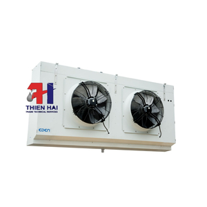
DÀN LẠNH EDEN DÒNG FEME
Vui lòng gọi

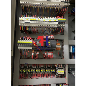
VỆ SINH, BẢO TRÌ HỆ THỐNG LẠNH CÔNG NGHIỆP
Vui lòng gọi

VỆ SINH DÀN NÓNG ( DÀN NGƯNG ) THƯƠNG HIỆU EDEN
Vui lòng gọi
SỬA CHỮA MÁY NÉN BITZER 34HP TẠI WINMART QUY NHƠN
Vui lòng gọi

Gối đỡ GD 200 GOMAX
Vui lòng gọi

Gối đỡ GD 150 GOMAX
Vui lòng gọi

Gối đỡ GD 100 GOMAX
Vui lòng gọi

Ống gân xoắn HDPE D90/112 Việt Nhật
37,050 đ
57,000 đ
Ống gân xoắn HDPE D125/160 Việt Nhật
65,975 đ
101,500 đ

Ống gân xoắn HDPE D100/130 Việt Nhật
40,950 đ
63,000 đ

Ống gân xoắn HDPE D150/195 Việt Nhật
98,800 đ
152,000 đ

Ống gân xoắn HDPE D160/210 Việt Nhật
120,250 đ
185,000 đ

Ống gân xoắn HDPED200/260 Việt Nhật
186,550 đ
287,000 đ

Ống gân xoắn HDPE D175/230 Việt Nhật
149,500 đ
230,000 đ

Ống gân xoắn HDPE D250/320 Việt Nhật
373,750 đ
575,000 đ

Gối đỡ GD 90 GOMAX
Vui lòng gọi
Măng sông MS 200 GOMAX
85,000 đ
Gối đỡ GD 80 GOMAX
Vui lòng gọi

Măng sông MS 175 GOMAX
75,000 đ
