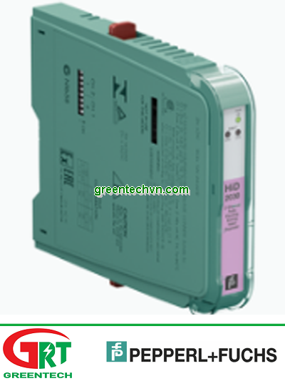

SMART Transmitter Power Supply HiD2030
- 2-channel isolated barrier
- 24 V DC supply (bus powered)
- 2-wire SMART transmitters or current sources
- Usable as signal splitter (1 input and 2 outputs)
- Dual output 4 mA ... 20 mA or 1 V ... 5 V
- Line fault detection (LFD)
- Up to SIL 2 acc. to IEC 61508
- Datasheet
- Documents
- CAD+CAE
- Approvals+Certificates
Download the complete datasheet as a PDF:
Datasheet excerpt: Technical data of HiD2030
| General specifications | ||
|---|---|---|
| Signal type | Analog input | |
| Supply | ||
| Connection | SL1: 1a(-), 1b(-); 2a(+), 2b(+) | |
| Rated voltage | 20.4 ... 30 V via Termination Board | |
| Rated current | 60 mA at 24 V, 20 mA output (per channel) | |
| Power dissipation | 1.05 W at 24 V (per channel) | |
| Input | ||
| Connection | SL2: 5a(+), 5b, 7a(-); 1a(+), 1b, 3b(-) | |
| Input current | 4 ... 20 mA , current limit 26 mA typ. | |
| Input resistance | 40 Ω , for current source | |
| Ripple | 10 mV eff | |
| Voltage | min. 15.5 V at 20 mA | |
| Communication | pass-through of HART signal to safe area The current sink terminals 4, 7 and 5, 6 do not pass the HART signal to safe area. | |
| Output | ||
| Connection | SL1: 8a(+), 7a(-); 10a(+), 9a(-) | |
| Load | 0 ... 650 Ω | |
| Output signal | 4 ... 20 mA or 1 ... 5 V (on 250 Ω, 0.1 % internal shunt) | |
| Ripple | 10 mV eff on a load of 250 Ω | |
| Response time | 70 ms , 10 ... 90 % step change | |
| Signal level | no fault: 1 mA ... 23.5 mA input current fault detection: < 0.2 mA or > 24 mA input current | |
| Error message output | ||
| Connection | SL1: 6b | |
| Output type | open collector transistor (common to both channels) fault bus signal, collective error message | |
| Transfer characteristics | ||
| Calibrated accuracy | < ± 0.1 % of full-scale value (current output) | |
| Influence of temperature | < ± 0.01 %/ K | |
| Frequency range | communication channel: 0.5 ... 40 kHz within 3 db, (-6 db at 100 kHz), Tx to output and output to Tx, suitable for use with SMART transmitters using HART or similar protocol | |
| Influence of load | < ± 0.1 % of full-scale value from 0 ... 650 Ω | |
| Linearity | < ± 0.05 % of full-scale value | |
| Directive conformity | ||
| Electromagnetic compatibility | ||
| Directive 2004/108/EC | EN 61326-1:2006 | |
| Conformity | ||
| Electromagnetic compatibility | NE 21:2006 For further information see system description. | |
| Degree of protection | IEC 60529 | |
| Ambient conditions | ||
| Ambient temperature | -20 ... 60 °C (-4 ... 140 °F) | |
| Mechanical specifications | ||
| Degree of protection | IP20 | |
| Mass | approx. 140 g | |
| Dimensions | 18 x 106 x 128 mm (0.7 x 4.2 x 5 inch) | |
| Mounting | on Termination Board | |
| Data for application in connection with hazardous areas | ||
| EC-Type Examination Certificate | CESI 02 ATEX 086 , for additional certificates see www.pepperl-fuchs.com | |
| Group, category, type of protection |
II (1)G [Ex ia Ga] IIC ,
II (1)D [Ex ia Da] IIIC | |
| Statement of conformity | PF 11 CERT 2109 X , observe statement of conformity | |
| Group, category, type of protection, temperature class |
II 3G Ex nA IIC T4 Gc [device in zone 2] | |
| Directive conformity | ||
| Directive 94/9/EC | EN 60079-0:2009, EN 60079-11:2007, EN60079-15:2005 , EN 60079-26:2007 , EN 61241-11:2006 | |
| International approvals | ||
| CSA approval | ||
| Control drawing | 366-005CS-12B (cCSAus) | |