| GESTRA Steam Systems | |||
| Issue Date: 11/08 | |||
| Product Range B | |||
| Compact System for Level Monitoring | |||
| NRGT 26-1 | |||
| NRGT 26-1S For Marine Applications | |||
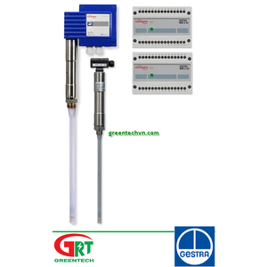
| NRGT 26-1 | |||
| NRGT 26-1S | |||
| Description | |||
| The compact system NRGT 26-1 works according to the capacitance measurement principle. The NRGT 26-1 is designed for signalling different levels in conductive and non-conductive liquids: | |||
| n Water level maintained within the control band defined by two preset limits. | |||
| The NRGT 26-1 has a level transmitter integrated in the terminal box which produces a standard output signal of 4-20 mA. External switchgear is not required. | |||
| Function | |||
| The principle of capacitance measurement is applied to determine the level. The electrode rod and the vessel wall form a capacitor. If the level of the dielectric located between the two capacitor plates changes, the current which flows through the plates changes proportionally to the level. A dielectric is defined as an insulating substance, which excludes many liquids such as water. In order to receive a useful measuring result the measuring rod, which is completely submerged in the liquid, must be completely insulated. After calibration of the zero point/measuring range (0 % - 100 %) of the control unit, the level can be read off from a remote display unit. The level measuring range can be changed during operation. | |||
| Design | |||
| NRGT 26-1: | |||
| Electrode with screwed connection ¾" BSP, EN ISO 228-1. | |||
| NRGT 26 -1S: | |||
| Flanged design for marine applications DN 50, PN 40, DIN 2635. | |||
| Technical Data | |||
| Type approval no. | |||
| NRGT 26-1: TÜV · WRS · 02-391 | |||
| NRGT 26-1 S: LR 98/20075 RINA ELE/30298/2 GL 99249-96HH BV 10617/AO BV NKK A-556 DNV A-8394 | |||
| KR HMB 06190-MS002 | |||
| Power consumption | |||
| 5 VA | |||
| Fuse | |||
| Thermal fuse T = 102 °C | |||
| Sensitivity | |||
| Range 1: Water ≥ 0.5 µ S/cm Range 2: Water ≥ 20 µ S/cm Range 3: Fuel oil EL e 2.3 | |||
| Output | |||
| 4-20 mA level-proportional. Volt-free, max. load 500 Ω | |||
| Indicators and adjustors | |||
| 2 red LEDs for signalling “Level 0 %” or “Level 100 %” within the measuring range, | |||
| 1 green LED for signalling “Level between 0 % and 100 %” of measuring range. | |||
| 1 code switch for selecting the measuring range. | |||
| 2 trimmer potentiometers for small-percentage adjust- ment of the measuring range. | |||
| 2 terminal lugs for voltage metering. | |||
| Cable entry | |||
| Cable gland with integral cable clamp | |||
| M 20 (PG 16) (2 x) | |||
| Protection | |||
| IP 65 to DIN EN 40050 | |||
| Max. admissible ambient temperature | |||
| 70 °C | |||
| Weight | |||
| NRGT 26-1: Approx. 1.8 kg NRGT 26-1S: Approx. 8.0 kg | |||
| GESTRA NRGT 26-1 | |||
| GESTRA Steam Systems | |||
| Service pressure | |||
| 32 bar g at 238°C | |||
| Connection | |||
| NRGT 26-1: Screwed ¾", EN ISO 228-1 NRGT 26-1S: Flanged DN 50, PN 40, DIN 2635 | |||
| Materials | |||
| Body 3.2161 G AlSi8Cu3 | |||
| Cover tube 1.4301 X5CrNi18-10 | |||
| Flange 1.0460 P250GH | |||
| Measuring electrodes 1.4571 CrNiMoTi17-12-2 Electrode insulation PTFE | |||
| Spacer disc PTFE | |||
| (design for marine applications) | |||
| Wiring diagram | |||
| NRGT 26-1 NRGT 26-1S | |||
| DC | |||
| Supply | |||
| Mains supply | |||
| 230 V +/– 10 %, 50/60 Hz | |||
| 115 V +/– 10 %, 50/60 Hz (optional) 24 V +/– 10 %, 50/60 Hz (optional) | |||
| 1 2 3 4 5 | |||
| Thermal | |||
| 24 V d.c. (optional) | |||
| Overall length / measuring range | |||
| See table overleaf | |||
| 4-20 mA | |||
| Max. load 500 Ω | |||
| PE | |||
| Earthing screw in housing | |||
| L N | |||
| Mains | |||
| + – | |||
| 24 V DC | |||
| fuse | |||
| Compact System for Level Monitoring | |||
| NRGT 26-1 NRGT 26-1S | |||
| For Marine Applications | |||
| Dimensions | |||
| 173 | |||
| GESTRA Steam Systems | |||
| 173 | |||
| GESTRA Steam Systems | |||
| Important Notes | |||
| Cable required for wiring: flexible multi-core control cable, min. conductor size 1.5 mm2. | |||
| GESTRA NRGT 26-1 | |||
| GESTRA NRGT 26-1S | |||
| Order and Enquiry Specification | |||
| GESTRA Level electrode NRGT 26-1, PN 40 | |||
| Mains supply............................................................... | |||
| Connection............................................................. | |||
| Inspection............................................................. | |||
| Length supplied...................................................... mm | |||
| Fluid..................................................................... | |||
| GESTRA Level electrode NRGT 26-1 S, PN 40 for marine applications | |||
| Mains supply............................................................... | |||
| Connection............................................................. | |||
| Inspection............................................................. | |||
| Length supplied...................................................... mm | |||
| Fluid..................................................................... | |||
| The following test certificates can be issued on request, at extra cost: In accordance with DIN EN 10204-2.1, -2.2 and -3.1B. | |||
| All inspection requirements have to be stated with the order. After supply of the equipment certification cannot be established. For tests and inspection charges please consult us. | |||
| Key | |||
| 1 Flange PN 40, DN 50, DIN 2527 Flange PN 40, DN 100, DIN 2527 | |||
| 2 For the approval of the boiler standpipe with con- necting flange the relevant regulations must be | |||
| 3 Vent hole | |||
| 4 High water (HW) | |||
| 5 Electrode rod d = 15 mm | |||
| 6 Protection tube DN 80 | |||
| ! Reducer DIN 2616, part 2 | |||
| K - 88.9 x 3.2 - 42.4 x 2.6 W | |||
| c NRGT 26-1: Measuring range | |||
| d NRGT 26-1S: Max. length of installation at 238 °C | |||
| e NRGT 26-1S: Measuring range | |||
| ATEX (Atmosphère Explosible) | |||
| ment must not be used in potentially explosive areas. | |||
| Æ 42 | |||
| b c | |||
| Fig. 1 NRGT 26-1 | |||
| ¾" BSP | |||
| DN 50 | |||
| 4 | |||
| b = 70 | |||
| ¾" BSP to EN ISO 228-1 | |||
| b | c | ||
| 373 | 300 | ||
| 477 | 400 | ||
| 583 | 500 | ||
| 688 | 600 | ||
| 794 | 700 | ||
| 899 | 800 | ||
| 1004 | 900 | ||
| 1110 | 1000 | ||
| 1214 | 1100 | ||
| 1319 | 1200 | ||
| 1423 | 1300 | ||
| 1528 | 1400 | ||
| 1636 | 1500 | ||
| 2156 | 2000 | ||
| 1 | |||
| 2 | |||
| 3 | |||
| 5 | |||
| 6 | |||
| 0 | |||
| Æ 42 | |||
| | |||
| d e | |||
| | |||
| Fig. 2 NRGT 26-1 S | |||
| DN 20 | |||
| b = 70 | |||
| Flange DN 50, PN 40 | |||
| Æ 48.5 | |||
| Æ 42.5 | |||
| 1 | |||
| 2 | |||
| 4 | |||
| 5 | |||
| 0 | |||
| d | e | ||
| 316 | 275 | ||
| 420 | 375 | ||
| 526 | 475 | ||
| 631 | 575 | ||
| 737 | 675 | ||
| 842 | 775 | ||
| 947 | 875 | ||
| 1053 | 975 | ||
| 1157 | 1075 | ||
| 1262 | 1175 | ||
| 1366 | 1275 | ||
| 1471 | 1375 | ||
| 1579 | 1475 | ||
| 2099 | 1975 | ||
| Supply in accordance with our general terms | |||
| of business. | |||
| Æ 20 | |||
| Fig. 3 Protection tube for installation of electrode inside the boiler | |||
| Fig. 4 External measuring pot | |||
| DN 20 | |||
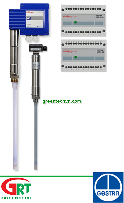
NRGT 26-1 | Gestra | Compact System for Level Monitoring | Hệ thống báo mức | Gestra Vietnam
Mã SP: RK86 A5801 | Gestra
Giá bán : Vui lòng gọi
Số lượng:
NRGT 26-1 | Gestra | Compact System for Level Monitoring | Hệ thống báo mức | Gestra Vietnam
Thông tin người bán
Công ty TNHH Thương mại dịch vụ GREENTECH
33 Đường DC5, Phường Sơn Kỳ, Quận Tân Phú, Tp.HCM
Hotline: 0935 04 1313
Email: sales@greentechvn.com
CHI TIẾT
THÔNG SỐ KỸ THUẬT
GESTRA Valves

For decades, GESTRA products have epitomised superior energy efficiency and reliability. They satisfy the most demanding requirements for reliable, loss-free operation, while of course also being maintenance-friendly and offering easy and convenient operation and control.
SẢN PHẨM TƯƠNG ĐƯƠNG

LIÊN HỆ
- Công ty TNHH TM DV GREENTECH là nhà XNK hàng đầu và là nhà cung cấp chuyên nghiệp các mặt hàng tự động, thiết bị điện và điện công nghiệp,.... Bên cạnh đó chúng tôi là nhà thực hiện các giải pháp tích hợp trong công nghiêp, dân dụng, xây dựng,... Chúng tôi đáp ứng mọi xu hướng công nghiệp hóa, hiện đại hóa hiện nay
Liên hệ cho chúng tôi để CÓ thông tin mà Quý khách CẦN.
< SALE & TECHNICAL SUPPORT >
< PROJECT SUPPORT >
Email : sales@greentechvn.com
Email : sales@greentechvn.com
-------------------------------------------------------------------
Nireco Vietnam | Pepperl + Fuchs Vietnam | Kikusui Vietnam | Danfoss Vietnam | Schmersal Vietnam | Meanwell Vietnam | Riken Keiki Vietnam | Bin Master Vietnam | Eclipse Vietnam | Optech Vietnam | | Idem Safety Switch Vietnam | Manostar Vietnam | Sew-Eurodrive Vietnam | Samson Vietnam | Lafert Vietnam | Sunon Vietnam | Mc Donnell Miller Vietnam | NSD Vietnam| Hitrol Vietnam | LS Vietnam | TDE Macno Vietnam | Parker Vietnam | Metrix Vietnam | | | Bacharach Vietnam | | Showa Denki Vietnam | S | | | | Tetra-K Electronic Vietnam | | | | | | Mitsubishi Vietnam | Siemens Vietnam | Omron Viet Nam | TPM Vietnam | Tecsis Vietnam | Wise Control Vietnam | Micro Process Controls Vietnam | Wika Vietnam | Asahi Gauge Vietnam | TemPress Vietnam | Itec Vietnam | Konics Vietnam | Ashcroft Vietnam | Ametek Vietnam – Afriso Vietnam | LS Industrial Vietnam | RS Automation Vietnam | Balluff Vietnam | Baumer Vietnam | Kuppler Vietnam | Pulsotronics Vietnam | Leuze Vietnam | Microsonic Vietnam | AST Vietnam | Tempsen Vietnam | STS Vietnam | Micro Dectector Vietnam | Proxitron Vietnam | Microsens Vietnam | Towa Seiden Vietnam | Promesstec Vietnam | Ski Vietnam | Eltra Vietnam | Hohner Vietnam | Posital Vietnam | Elap Vietnam | Beisensors Vietnam | Newall Vietnam | Dotech Vietnam | Watlow Vietnam | Bihl Weidemann Vietnam | Prosoft Vietnam | ICP DAS Vietnam | Beckhoff Vietnam | Keller M S R Vietnam | IRCON Vietnam | Raytek Vietnam | Kimo Vietnam | YSI Vietnam | Jenco Vietnam | Tekhne Vietnam | Atago Vietnam | E Instrument Vietnam | IMR Vietnam | Netbiter Viêt Nam | FMS Vietnam | Unipulse Vietnam | Migun Vietnam | Sewha Vietnam | HBM Vietnam | Pilz Vietnam | Dold Vietnam | | Puls Vietnam | Microsens Vietnam | Controller Sensor Vietnam | Mark|10 Vietnam | Schmidt Vietnam | Bernstein Vietnam | Celduc Vietnam | Univer Vietnam | Waicom Vietnam | Aignep Vietnam | Top Air Vietnam | Burket Vietnam | | JJ Automation Vietnam | Somas Vietnam | Delta Elektrogas Vietnam | Pentair Vietnam | Auma Vietnam | Sipos Artorik Vietnam | Flowserve Vietnam | Sinbon Vietnam | Setra Vietnam | Yottacontrok Vietnam | Sensor Tival Vietnam | Vaisala Vietnam | Crouzet Vietnam | RheinTacho Vietnam | Cityzen Seimitsu Vietnam | Flowserve Vietnam | Greatork Vietnam | PS Automation Vietnam | Bettis Vietnam | Sinbon Vietnam | Setra Vietnam | Laurel Vietnam | Datapaq Vietnam | EE Electronik Vietnam | Banico Vietnam | Sinfonia Vietnam | Digmesa Vietnam | Alia Vietnam | Flowline Vietnam | Brook Instrument Vietnam | Dakota Instrument Vietnam | Diehl Metering Vietnam | Stego Vietnam | Rotronic Vietnam | Hopeway Vietnam | Beko Vietnam | Matsui Vietnam | Westec Vietnam | Sometech Vietnam | Offshore Vietnam | DCbox Vietnam | Fanuc Vietnam | KollMorgen Vietnam | Endress & Hauser Vietnam | Metso Automation Vietnam | MKS Instruments Vietnam | Teledyne Instruments Vieatnam | Badger Meter Vietnam | Hirschmann Vietnam | Servo Mitsubishi Vietnam | SCR SA Việt Nam | Biotech Flow Meter Việt Nam | Thermo Electric Việt Nam | Siko Việt Nam | Klinger Việt Nam | HK Instrument Việt Nam | Magnetrol Viet Nam | Lika Viet Nam | Setra Viet Nam | Kistler Viet Nam | Renishaw Viet Nam | Mindmen Vietnam |
-------------------------------------------------------------------
Sản phẩm cùng loại
Rơle điện tử SCHNEIDER EOCR3EZ-80AUH
Vui lòng gọi
Phin lọc DML 306 Danfoss
Vui lòng gọi
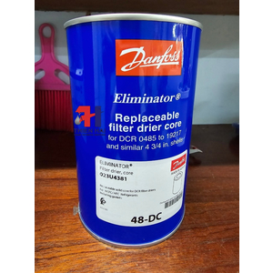
ĐÁ LỌC 48-DC DANFOSS
Vui lòng gọi
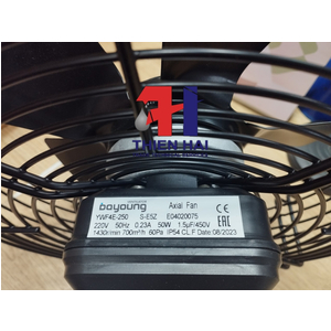
Quạt dàn lạnh, quạt dàn nóng YWF4E-250 S-E5Z
Vui lòng gọi
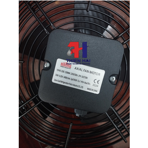
QUẠT DÀN NÓNG, QUẠT DÀN LẠNH YDF4E-250S 250MM
Vui lòng gọi
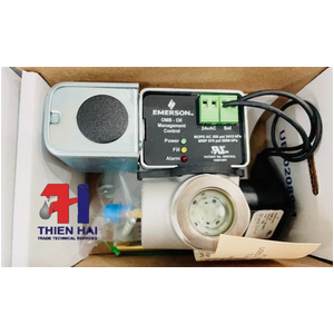
PHAO DẦU ĐIỆN TỬ OMB-Oil JB24
Vui lòng gọi
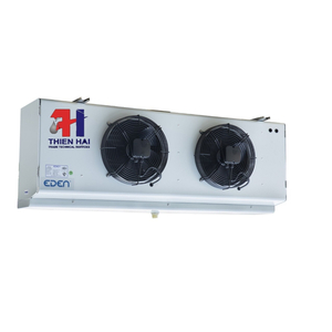
DÀN LẠNH EDEN FEME LT6
Vui lòng gọi

DÀN LẠNH EDEN FEME PD6 GIÁ TỐT
Vui lòng gọi
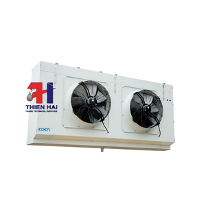
DÀN LẠNH EDEN DÒNG FEM
Vui lòng gọi

DÀN LẠNH EDEN DÒNG FEME
Vui lòng gọi

VỆ SINH, BẢO TRÌ HỆ THỐNG LẠNH CÔNG NGHIỆP
Vui lòng gọi

VỆ SINH DÀN NÓNG ( DÀN NGƯNG ) THƯƠNG HIỆU EDEN
Vui lòng gọi
SỬA CHỮA MÁY NÉN BITZER 34HP TẠI WINMART QUY NHƠN
Vui lòng gọi

Hộp nối dây - ABO150x150 - HDV
23,513 đ

Hộp nối dây - ABO200x200 - HDV
41,800 đ
Hộp nối dây - ABO100x100 - HDV
12,854 đ