| Ordering details | |
| Product type description | AES 1235 |
| Article number | 101170049 |
| EAN code | 4030661297118 |
| eCl@ss | 27-37-19-01 |
| Approval | |
| Approval |
BG
USA/CAN
|
| Classification | |
| Standards | EN ISO 13849-1, IEC 61508 |
| PL | up d |
| Control category | up 3 |
| PFH value | 1.0 x 10⁻⁷/h |
| - notice | up to max. 50.000 switching cycles/year and at max. 80% contact load |
| SIL | 2 |
| Mission time | 20 Years |
| Global Properties | |
| Product name | AES 123x |
| Standards | IEC/EN 60204-1, IEC 60947-5-3, EN 954-1, BG-GS-ET-14, BG-GS-ET-20 |
| Compliance with the Directives (Y/N)
| Yes |
| Climatic stress | EN 60068-2-3, BG-GS-ET-14 |
| Mounting | snaps onto standard DIN rail to EN 60715 |
| Terminal designations | IEC/EN 60947-1 |
| Materials | |
| - Material of the housings | Plastic, glass-fibre reinforced thermoplastic, ventilated |
| - Material of the contacts | Ag-Ni, 0,2 µm gold flashed |
| Weight | 160 g |
| Start conditions | Automatic or Start button |
| Start input (Y/N) | No |
| Feedback circuit (Y/N) | Yes |
| Start-up test (Y/N) | No |
| Reset after disconnection of supply voltage (Y/N) | Yes |
| Automatic reset function (Y/N) | Yes |
| Reset with edge detection (Y/N) | No |
| Pull-in delay | |
| - ON delay with automatic start | adjustable 0,1 / 1.0 s |
| Drop-out delay | |
| - Drop-out delay in case of emergency stop | < 50 ms |
| Mechanical data | |
| Connection type | Screw connection |
| Cable section | |
| - Min. Cable section | 0,25 mm² |
| - Max. Cable section | 2.5 mm² |
| Pre-wired cable | rigid or flexible |
| Tightening torque for the terminals | 0,6 Nm |
| Detachable terminals (Y/N) | No |
| Mechanical life | 20.000.000 operations |
| Electrical lifetime | 150.000 operations for 230 VAC, 5 A (cos φ = 1) |
| restistance to shock | 30 g / 11 ms |
| Resistance to vibration To EN 60068-2-6 | 10...55 Hz, Amplitude 0,35 mm, ± 15 % |
| Ambient conditions | |
| Ambient temperature | |
| - Min. environmental temperature | 0°C |
| - Max. environmental temperature | +55 °C |
| Storage and transport temperature | |
| - Min. Storage and transport temperature | −25 °C |
| - Max. Storage and transport temperature | +70 °C |
| Protection class | |
| - Protection class-Enclosure | IP40 |
| - Protection class-Terminals | IP20 |
| - Protection class-Clearance | IP54 |
| Air clearances and creepage distances To IEC/EN 60664-1 | |
| - Rated impulse withstand voltage Uimp | 4.8 kV |
| - Overvoltage category | III To VDE 0110 |
| - Degree of pollution | 2 To VDE 0110 |
| Electromagnetic compatibility (EMC) | |
| EMC rating | 10 V/m |
| Electrical data | |
| Rated DC voltage for controls | |
| - Min. rated DC voltage for controls | 20.4 V |
| - Max. rated DC voltage for controls | 27.6 V |
| Rated AC voltage for controls, 50 Hz | |
| - Min. rated AC voltage for controls, 50 Hz | - |
| - Max. rated AC voltage for controls, 50 Hz | - |
| Rated AC voltage for controls, 60 Hz | |
| - Min. rated AC voltage for controls, 60 Hz | - |
| - Max. rated AC voltage for controls, 60 Hz | - |
| Contact resistance | max. 100 mΩ |
| Power consumption | < 5 W |
| Type of actuation | DC |
| Switch frequency | 1 Hz |
| Rated insulation voltage Ui | 250 V |
| Rated operating voltage Ue | 24 VDC ±15% |
| Thermal test current Ithe | 6 A |
| Operating current Ie | 0,2 A |
| Electronic protection (Y/N) | No |
| Inputs | |
| Monitored inputs | |
| - Short-circuit recognition (Y/N) | optional |
| - Wire breakage detection (Y/N) | Yes |
| - Earth connection detection (Y/N) | Yes |
| Number of shutters | adjustable 1 piece -> 0 piece |
| Number of openers | adjustable 1 piece -> 2 piece |
| Input resistance | approx. 4000 Ω at GND |
| Input signal "1" | 10 ... 30 VDC |
| Input signal "0" | 0 ... 2 VDC |
| Cable length | 1000 m with 0,75 mm² (for Rated voltage) |
| Outputs | |
| Stop category | 0 |
| Number of safety contacts | 2 piece |
| Number of auxiliary contacts | 0 piece |
| Number of signalling outputs | 2 piece |
| Switching capacity | |
| - Switching capacity of the safety contacts | min. 10 mA, max. 6 A |
| - Switching capacity of the signaling/diagnostic outputs | min. Ue −4V / Y1, Y2: max. 100 mA |
| Fuse rating | |
| - Protection of the safety contacts | 6 A gG D-fuse |
| - Fuse rating for the signaling/diagnostic outputs | short-circuit proof, p-type |
| Signalling output | Y1: Authorized operation, safety contacts on;2 YNo authorised operation off:, safety contacts |
| Utilisation category To EN 60947-5-1 | AC-15: 230 V / 3 ADC-13: 24 V / 2 A |
| Number of undelayed semi-conductor outputs with signaling function | 2 piece |
| Number of undelayed outputs with signaling function (with contact) | 0 piece |
| Number of delayed semi-conductor outputs with signaling function. | 0 piece |
| Number of delayed outputs with signalling function (with contact). | 0 piece |
| Number of secure undelayed semi-conductor outputs with signaling function | 0 piece |
| Number of secure, undelayed outputs with signaling function, with contact. | 0 piece |
| Number of secure, delayed semi-conductor outputs with signaling function | 0 piece |
| Number of secure, delayed outputs with signaling function (with contact). | 0 piece |
| LED switching conditions display | |
| LED switching conditions display (Y/N) | Yes |
| Number of LED´s | 1 piece |
| Integral system diagnosis ISD | |
| Integral system diagnosis ISD | |
| - The following faults are registered by the safety monitoring modules and indicated by ISD | |
| - Failure of door contacts to open or close | |
| - Cross-wire or short-circuit monitoring of the switch connections | |
| - Interruption of the switch connections | |
| - Failure of the safety relay to pull-in or drop-out | |
| - Fault on the input circuits or the relay control circuits of the safety monitoring module | |
| Miscellaneous data | |
| Applications |
Safety sensor
Guard system |
| Dimensions | |
| Dimensions | |
| - Width | 22.5 mm |
| - Height | 100 mm |
| - Depth | 121 mm |
| notice | |
| Inductive loads (e.g. contactors, relays, etc.) are to be suppressed by means of a suitable circuit. | |
| notice - Wiring example | |
| To secure a guard door up to PL 3 and Category #03# | |
| Monitoring 1 guard door(s), each with a magnetic safety sensor of the BNS range | |
| The feedback circuit monitors the position of the contactors K3 and K4. | |
| Start push button A start push button (NO) can optionally be connected into the feedback circuit. With the guard door closed, the enabling paths are then not closed until the start push button has been operated. | |
| If neither start button nor feedback circuit are connected, a jumper connection must be mounted between X1 and A1. | |
| If only one external relay or contactor is used to switch the load, the system can be classified in Control Category 3 to EN 954-1, if exclusion of the fault “Failure of the external contactor” can be substantiated and is documented, e.g. by using a reliable down-rated contactor. A second contactor leads to an increase in the level of security by redundant switching to switch the load off. | |
| Modification for 2 NC contacts:The safety monitoring module can be modified to monitor two NC contacts by bridging the terminals A1 and X2. The short-circuit recognition between connections then becomes inoperative. | |
| Expansion of enable delay time:The enable delay time can be increased from 0,1 s to 1 s by changing the position of a jumper link connection under the cover of the unit. | |
| The wiring diagram is shown with guard doors closed and in de-energised condition. | |
| The ISD tables (Intergral System Diagnostics) for analysis of the fault indications and their causes are shown in the appendix. | |
| K.A. Schmersal GmbH & Co. KG, Möddinghofe 30, D-42279 WuppertalThe data and values have been checked throroughly. Technical modifications and errors excepted.Generiert am 04.08.2016 - 04:58:49h Kasbase 3.2.4.F.64I | |
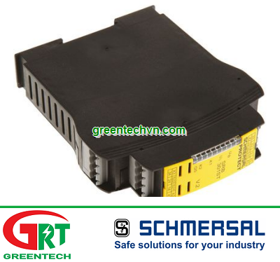
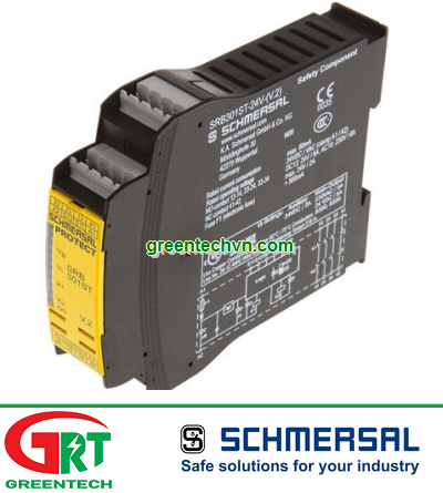
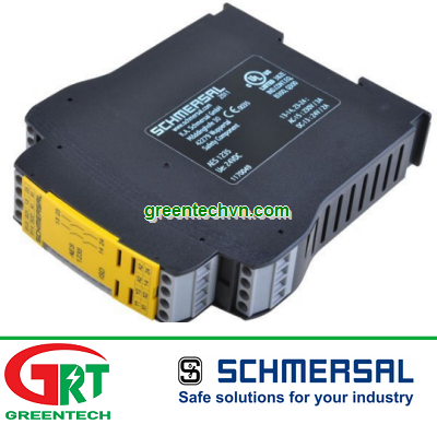
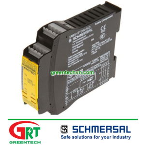
AES 1235 Schmersal | AES1235-24VDC | Schmersal | Rơ-le an toàn AES 1235 | Safety relay AES 1235
Mã SP: AES 1235
Giá bán : Vui lòng gọi
Số lượng:
AES 1235 Schmersal | AES1235-24VDC | Schmersal | Rơ-le an toàn AES 1235 | Safety relay AES 1235
Thông tin người bán
CÔNG TY TNHH THƯƠNG MẠI DỊCH VỤ GREENTECH
33 Đường DC5, Phường Tây Thạnh, Tp.HCM, Việt Nam
Hotline: 0935 04 1313
Email: nhan@greentechvn.com
CHI TIẾT


THÔNG SỐ KỸ THUẬT
SẢN PHẨM TƯƠNG ĐƯƠNG
LIÊN HỆ
- Công ty TNHH TM DV GREENTECH là nhà XNK hàng đầu và là nhà cung cấp chuyên nghiệp các mặt hàng tự động, thiết bị điện và điện công nghiệp,.... Bên cạnh đó chúng tôi là nhà thực hiện các giải pháp tích hợp trong công nghiêp, dân dụng, xây dựng,... Chúng tôi đáp ứng mọi xu hướng công nghiệp hóa, hiện đại hóa hiện nay
Liên hệ cho chúng tôi để CÓ thông tin mà Quý khách CẦN.
< SALE & TECHNICAL SUPPORT >
< PROJECT SUPPORT >
Email : sales@greentechvn.com
Email : sales@greentechvn.com
-------------------------------------------------------------------
Kikusui Vietnam | |Schmersal Vietnam | Meanwell Vietnam | Riken Keiki Vietnam | Bin Master Vietnam | Eclipse Vietnam | Optech Vietnam | | Idem Safety Switch Vietnam | Manostar Vietnam | Sew-Eurodrive Vietnam | Samson Vietnam | Lafert Vietnam | Sunon Vietnam | Mc Donnell Miller Vietnam | NSD Vietnam| Hitrol Vietnam | LS Vietnam | TDE Macno Vietnam | Parker Vietnam | Metrix Vietnam | | | Bacharach Vietnam | | Showa Denki Vietnam | S | | | | Tetra-K Electronic Vietnam | | | | | | Mitsubishi Vietnam | Siemens Vietnam | Omron Viet Nam | TPM Vietnam | Tecsis Vietnam | Wise Control Vietnam | Micro Process Controls Vietnam | Wika Vietnam | Asahi Gauge Vietnam | TemPress Vietnam | Itec Vietnam | Konics Vietnam | Ashcroft Vietnam | Ametek Vietnam – Afriso Vietnam | LS Industrial Vietnam | RS Automation Vietnam | Balluff Vietnam | Baumer Vietnam | Kuppler Vietnam | Pulsotronics Vietnam | Leuze Vietnam | Microsonic Vietnam | AST Vietnam | Tempsen Vietnam | STS Vietnam | Micro Dectector Vietnam | Proxitron Vietnam | Microsens Vietnam | Towa Seiden Vietnam | Promesstec Vietnam | Ski Vietnam | Eltra Vietnam | Hohner Vietnam | Posital Vietnam | Elap Vietnam | Beisensors Vietnam | Newall Vietnam | Dotech Vietnam | Watlow Vietnam | Bihl Weidemann Vietnam | Prosoft Vietnam | ICP DAS Vietnam | Beckhoff Vietnam | Keller M S R Vietnam | IRCON Vietnam | Raytek Vietnam | Kimo Vietnam | YSI Vietnam | Jenco Vietnam | Tekhne Vietnam | Atago Vietnam | E Instrument Vietnam | IMR Vietnam | Netbiter Viêt Nam | FMS Vietnam | Unipulse Vietnam | Migun Vietnam | Sewha Vietnam | HBM Vietnam | Pilz Vietnam | Dold Vietnam | | Puls Vietnam | Microsens Vietnam | Controller Sensor Vietnam | Mark|10 Vietnam | Schmidt Vietnam | Bernstein Vietnam | Celduc Vietnam | Univer Vietnam | Waicom Vietnam | Aignep Vietnam | Top Air Vietnam | Burket Vietnam | | JJ Automation Vietnam | Somas Vietnam | Delta Elektrogas Vietnam | Pentair Vietnam | Auma Vietnam | Sipos Artorik Vietnam | Flowserve Vietnam | Sinbon Vietnam | Setra Vietnam | Yottacontrok Vietnam | Sensor Tival Vietnam | Vaisala Vietnam | Crouzet Vietnam | RheinTacho Vietnam | Cityzen Seimitsu Vietnam | Flowserve Vietnam | Greatork Vietnam | PS Automation Vietnam | Bettis Vietnam | Sinbon Vietnam | Setra Vietnam | Laurel Vietnam | Datapaq Vietnam | EE Electronik Vietnam | Banico Vietnam | Sinfonia Vietnam | Digmesa Vietnam | Alia Vietnam | Flowline Vietnam | Brook Instrument Vietnam | Dakota Instrument Vietnam | Diehl Metering Vietnam | Stego Vietnam | Rotronic Vietnam | Hopeway Vietnam | Beko Vietnam | Matsui Vietnam | Westec Vietnam | Sometech Vietnam | Offshore Vietnam | DCbox Vietnam | Fanuc Vietnam | KollMorgen Vietnam | Endress & Hauser Vietnam | Metso Automation Vietnam | MKS Instruments Vietnam | Teledyne Instruments Vieatnam | Badger Meter Vietnam | Hirschmann Vietnam | Servo Mitsubishi Vietnam | SCR SA Việt Nam | Biotech Flow Meter Việt Nam | Thermo Electric Việt Nam | Siko Việt Nam | Klinger Việt Nam | HK Instrument Việt Nam | Magnetrol Viet Nam | Lika Viet Nam | Setra Viet Nam | Kistler Viet Nam | Renishaw Viet Nam | Mindmen Vietnam |
-------------------------------------------------------------------
Sản phẩm cùng loại