| Datasheet - SRB 301MC-24VGuard door monitors and Safety control modules for Emergency Stop applications / General Purpose safety controllers (Series PROTECT SRB) / SRB 301MC
Preferred typ | |
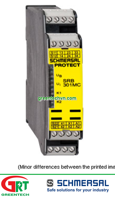
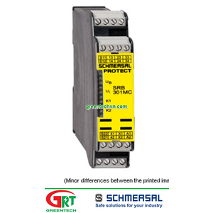
(Minor differences between the printed image and the original product may exist!) | • Fit for signal evaluation of outputs of safety magnetic switches • 3 safety contacts, STOP 0 • 1 Signalling output • Suitable for signal processing of outputs connected to potentials (AOPDs), e.g. safety light grids/curtains • Suitable for signal processing of potential-free outputs, e.g. emergency stop command devices, position switches and solenoid interlocks |
| Ordering details | |
| Product type description | SRB 301MC-24V |
| Article number | 101190684 |
| EAN code | 4250116202249 |
| eCl@ss | 27-37-19-01 |
| Approval | |
| Approval |
BG
USA/CAN
|
| Classification | |
| Standards | EN ISO 13849-1, IEC 61508, EN 60947-5-1 |
| PL | up e (STOP 0) |
| Control category | up 4 (STOP 0) |
| DC | 99% (STOP 0) |
| CCF | > 65 points |
| PFH value | ≤ 2,0 x 10⁻⁸/h (STOP 0) |
| SIL | up 3 (STOP 0) |
| Mission time | 20 Years |
| - notice | The PFH value is applicable for the combinations listed in the table for contact load (K) (current through enabling paths) and switching cycle number (n-op/y).In case of 365 operating days per year and a 24-hour operation, this results in the specified switching cycle times (t-cycle) for the relay contacts. Diverging applications on request.
|
| Global Properties | |
| Product name | SRB 301MC |
| Standards | IEC/EN 60204-1, EN 60947-5-1, EN ISO 13849-1, IEC 61508 |
| Compliance with the Directives (Y/N)
| Yes |
| Climatic stress | EN 60068-2-78 |
| Mounting | snaps onto standard DIN rail to EN 60715 |
| Terminal designations | IEC/EN 60947-1 |
| Materials | |
| - Material of the housings | Plastic, glass-fibre reinforced thermoplastic, ventilated |
| - Material of the contacts | , Ag-Ni, self-cleaning, positive action |
| Weight | 250 g |
| Start conditions | Automatic or Start button |
| Start input (Y/N) | Yes |
| Feedback circuit (Y/N) | Yes |
| Start-up test (Y/N) | No |
| Automatic reset function (Y/N) | Yes |
| Reset with edge detection (Y/N) | No |
| Pull-in delay | |
| - ON delay with automatic start | 100 ms |
| - ON delay with reset button | 20 ms |
| Drop-out delay | |
| - Drop-out delay in case of power failure | 80 ms |
| - Drop-out delay in case of emergency stop | ≤ 20 ms |
| Mechanical data | |
| Connection type | Screw connection |
| Cable section | |
| - Min. Cable section | 0,25 mm² |
| - Max. Cable section | 2.5 mm² |
| Pre-wired cable | rigid or flexible |
| Tightening torque for the terminals | 0,6 Nm |
| Detachable terminals (Y/N) | No |
| Mechanical life | 10.000.000 operations |
| Electrical lifetime | Derating curve available on request |
| restistance to shock | 30 g / 11 ms |
| Resistance to vibration To EN 60068-2-6 | 10...55 Hz, Amplitude 0,35 mm, ± 15 % |
| Ambient conditions | |
| Ambient temperature | |
| - Min. environmental temperature | −25 °C |
| - Max. environmental temperature | +60 °C |
| Storage and transport temperature | |
| - Min. Storage and transport temperature | −40 °C |
| - Max. Storage and transport temperature | +85 °C |
| Protection class | |
| - Protection class-Enclosure | IP40 |
| - Protection class-Terminals | IP20 |
| - Protection class-Clearance | IP54 |
| Air clearances and creepage distances To IEC/EN 60664-1 | |
| - Rated impulse withstand voltage Uimp | 4 kV |
| - Overvoltage category | III To IEC/EN 60664-1 |
| - Degree of pollution | 2 To IEC/EN 60664-1 |
| Electromagnetic compatibility (EMC) | |
| EMC rating | conforming to EMC Directive |
| Electrical data | |
| Rated DC voltage for controls | |
| - Min. rated DC voltage for controls | 20.4 V |
| - Max. rated DC voltage for controls | 28.8 V |
| Rated AC voltage for controls, 50 Hz | |
| - Min. rated AC voltage for controls, 50 Hz | 20.4 V |
| - Max. rated AC voltage for controls, 50 Hz | 26.4 V |
| Rated AC voltage for controls, 60 Hz | |
| - Min. rated AC voltage for controls, 60 Hz | 20.4 V |
| - Max. rated AC voltage for controls, 60 Hz | 26.4 V |
| Contact resistance | max. 100 mΩ |
| Power consumption | 2 W; 4.9 VA |
| Type of actuation | AC/DC |
| Switch frequency | |
| Rated operating voltage Ue | 24 VDC −15% / +20%, residual ripple max. 10%24 VAC −15% / +10% |
| Operating current Ie | |
| Frequency range | 50 / 60 Hz |
| Electronic protection (Y/N) | Yes |
| Fuse rating for the operating voltage | Internal electronic trip, tripping current > 0,5 A, Reset after approximately 1 second/s |
| Current and tension on control circuits | |
| - S11, S12, S21, S22 | 24 VDC, Test current: 10 mA |
| Bridging in case of voltage drops | 80 ms |
| Inputs | |
| Monitored inputs | |
| - Short-circuit recognition (Y/N) | optional |
| - Wire breakage detection (Y/N) | Yes |
| - Earth connection detection (Y/N) | Yes |
| Number of shutters | 0 piece |
| Number of openers | 2 piece |
| Cable length | 1500 m with 1.5 mm²; 2500 m with 2.5 mm² |
| Conduction resistance | max. 40 Ω |
| Outputs | |
| Stop category | 0 / 1 |
| Number of safety contacts | 3 piece |
| Number of auxiliary contacts | 1 piece |
| Number of signalling outputs | 0 piece |
| Switching capacity | |
| - Switching capacity of the safety contacts | max. 250 VAC, 8 A ohmic (inductive in case of appropriate protective wiring) min. 10 V / 10 mA |
| - Switching capacity of the auxiliary contacts | 24 VDC, 2 A |
| Fuse rating | |
| - Protection of the safety contacts | 8 A slow blow |
| - Fuse rating for the auxiliary contacts | 2 A slow blow |
| Utilisation category To EN 60947-5-1 | AC-15: 230 V / 6 A DC-13: 24 V / 6 A |
| Number of undelayed semi-conductor outputs with signaling function | 0 piece |
| Number of undelayed outputs with signaling function (with contact) | 1 piece |
| Number of delayed semi-conductor outputs with signaling function. | 0 piece |
| Number of delayed outputs with signalling function (with contact). | 0 piece |
| Number of secure undelayed semi-conductor outputs with signaling function | 0 piece |
| Number of secure, undelayed outputs with signaling function, with contact. | 3 piece |
| Number of secure, delayed semi-conductor outputs with signaling function | 0 piece |
| Number of secure, delayed outputs with signaling function (with contact). | 0 piece |
| LED switching conditions display | |
| LED switching conditions display (Y/N) | Yes |
| Number of LED´s | 4 piece |
| LED switching conditions display | |
| - The integrated LEDs indicate the following operating states. | |
| - Position relay K1 | |
| - Position relay K2 | |
| - Supply voltage | |
| - Internal operating voltage Ui | |
| Miscellaneous data | |
| Applications |
Emergency-Stop button
Guard system
Pull-wire emergency stop switches
Safety light curtain
Safety sensor |
| Dimensions | |
| Dimensions | |
| - Width | 22.5 mm |
| - Height | 100 mm |
| - Depth | 121 mm |
| notice | |
| Inductive loads (e.g. contactors, relays, etc.) are to be suppressed by means of a suitable circuit. | |
| notice - Wiring example | |
| To secure a guard door up to PL 4 and Category #03# | |
| Monitoring 1 guard door(s), each with a magnetic safety sensor of the BNS range | |
| The feedback circuit monitors the position of the contactors Ka and Kb. | |
| Switch setting: The cross-wire short detection function (factory default) is programmed by means of the switch located underneath the front cover of the module:Pposition nQS (top): no cross-wire short protection, suitable for 1-channel applications and applications with outputs with potential in the control circuits. Position QS (bottom): cross-wire short protection, suitable for 2-channel applications without outputs with potential in the control circuits. | |
| For 1-channel control, connect NC contact to S11/S12 and bridge S12/S22 (QS-switch = nQS) | |
| Connect potential p-type outputs of safety light grids/curtains to S12/S22. The devices must have the same reference potential. (QS-switch = nQS) | |
| Automatic start: The automatic start is programmed by connecting the feedback circuit to the terminals X1/X2. If the feedback circuit is not required, establish a bridge | |
| The wiring diagram is shown with guard doors closed and in de-energised condition. | |
| Documents | |
| Operating instructions and Declaration of conformity (jp) 461 kB, 03.07.2013 | |
| Code: mrl_srb_301mc_jp | |
| Operating instructions and Declaration of conformity (fr) 374 kB, 24.10.2016 | |
| Code: mrl_srb_301mc_fr | |
| Operating instructions and Declaration of conformity (pl) 388 kB, 24.10.2016 | |
| Code: mrl_srb_301mc_pl | |
| Operating instructions and Declaration of conformity (en) 441 kB, 14.07.2016 | |
| Code: mrl_srb_301mc_en | |
| Operating instructions and Declaration of conformity (it) 371 kB, 24.10.2016 | |
| Code: mrl_srb_301mc_it | |
| Operating instructions and Declaration of conformity (br) 830 kB, 28.10.2010 | |
| Code: mrl_srb_301mc_br | |
| Operating instructions and Declaration of conformity (pt) 381 kB, 30.11.2016 | |
| Code: mrl_srb_301mc_pt | |
| Operating instructions and Declaration of conformity (es) 383 kB, 16.09.2016 | |
| Code: mrl_srb_301mc_es | |
| Operating instructions and Declaration of conformity (de) 431 kB, 14.07.2016 | |
| Code: mrl_srb_301mc_de | |
| Operating instructions and Declaration of conformity (nl) 361 kB, 08.07.2013 | |
| Code: mrl_srb_301mc_nl | |
| Wiring example (99) 17 kB, 04.08.2008 | |
| Code: ksrb3l18 | |
| TÜV certification (de, en) 596 kB, 05.07.2016 | |
| Code: z_srbp01 | |
| CCC certification (en) 739 kB, 24.07.2017 | |
| Code: q_srbp03 | |
| CCC certification (cn) 738 kB, 24.07.2017 | |
| Code: q_srbp04 | |
| EAC certification (ru) 833 kB, 05.10.2015 | |
| Code: q_6042p17_ru | |
| Images | |
Wiring example | |